1. Introduction
1.1 Overview
DeviceBit Platform (http://www.devicebit.com), a real-time data brokerage platform for the Internet of Things (IOT), provides most of its functionality via its Application Programming Interface (API), and makes it quick and easy to create your devices with applications and connect them to DeviceBit platform. It provides real-time data storage and remote control, which makes it easy for you to manage your devices in volume. The DeviceBit platform is not only an easy way to prototype new Internet-enabled devices, but also a service that helps companies bring products to market at scale.
DeviceBit platform is not only providing basic data analysis tools for series of research based on your data, but also providing real-time alert and notifications if some of your devices are abnormal. We have developed the Mobile DeviceBit App (Beta version) so you can manage your devices more conveniently.
1.2 Core Concepts
Our IOT architecture is composed of three nodes, i.e. Central Server -> Device ->Sensor&Controller, as shown in Pic.1.
.jpg)
Pic. 1 DeviceBit IOT Architecture
The Sensor is a kind of measuring instrument that also includes meters, or other measuring devices. The function of the sensor is to get the measurement you need. On the other hand, the instruments also can be controllable, such as the controller. The Device can both communicates with Sensors and Central servers. Its function is to transfer the measurement sent by the Sensor to the database on Central server. It can be hardware supporting several protocols (Modbus protocol, TCP/IP protocol or private protocol) or software running on your PC. The measurements are sent to the Central server via different networks, such as GPRS, Wi-Fi or Ethernet. The Central server has database running on it. All the data sent by the Sensor are stored respectively in the database.
2. Add A New Device
For getting started on DeviceBit platform, the first step is to add a new device.
Log into the IOT platform (If you don’t have the account you need to sign up first).
Register DeviceBit Account (www.devicebit.com)

Pic. 2 Sign Up
As shown in Pic2, go to My Devices -> Devices -> Add A device, fill in the information and then save.

Pic. 3 Create a new device
ID: The ID of the device, allocated by system automatically. It is unique for each device.
Type: The type of the device.
Ø Arduino: Arduino Board.
Ø Lw-board: The board developed by DeviceBit.
Ø Other: Other board.
Name: The name of the device.
Description: Description of the device.
Public: If your devices are public, other users can also view them and their measurement.
Location: The location of you device. Click on the location point on the Map.
3. Add a new sensor or controller
The next step is to add a new sensor or controller connected to your device.
3.1 Add a new sensor
As shown in Pic3, go to My Devices -> Sensors&Controllers ->Sensors, and then click on Add button to create a new sensor.
.jpg)
Pic.4 Add a new sensor
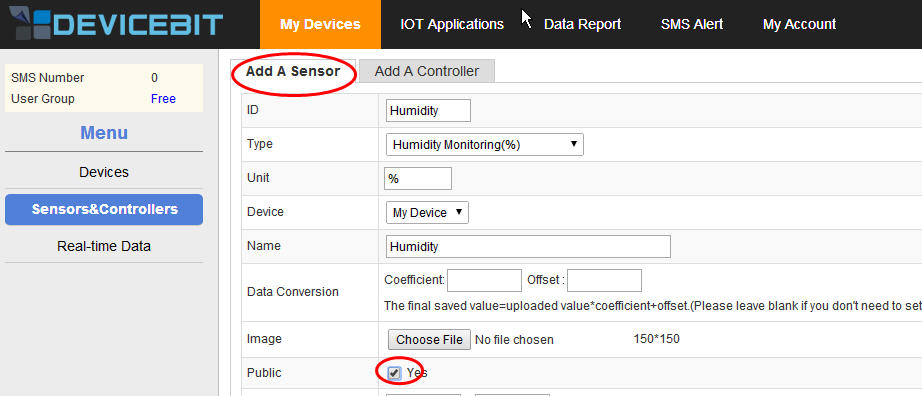
Pic.5 Create a new sensor
ID: The ID of the new sensor. It is unique for each sensor.
Type: The type of the new sensor.
Unit: The unit of the measurement.
Device: Select the device which the sensor to be connected to.
Name: The name of the new sensor.
Data Conversion: To calibrate your sensor’s measurement. You can fill in the Coefficient and offset if applicable.
Picture: Upload the picture of your sensor.
Public: If your sensors are public, other users can also view them and their measurement.
Normal range: The normal range of the sensor’s measurement. You can set it according to your actual need.
Overrange alarm: Turn it on and you will receive the alert by SMS or email when the sensor’s measurement is out of the range.
Data post period: The system indicates that the sensor is OFFLINE if it does not get the data posted by the sensor within every data post period set here.
Remark: Remark of the sensor.
3.2 Add a new controller
As shown in Pic4, go to My Devices -> Sensors&Controllers ->Controllers, and then click on Add button to create a new controller.
.jpg)
Pic.6 Add a new controller
.jpg)
Pic.7 Create a new controller
Fill in the related information and then click on Save.
The related parameters are explained as follows:
ID: The ID of the new controller. It is unique for each controller.
Name: The name of the new controller.
Device: To select the device which the controller is connected to.
Type: The type of the new controller, which can be switch control or numerical control. For switch type, 0 or 1 is used to control the switch. While for numerical type, the controller status is adjusted by different numerical values.
Max-value: The max-value for numerical type.
Min-value: The min-value for numerical type.
4. Data reports
DeviceBit platform provides basic data-analyzing tools so you can do a series of research based on your data stored in DeviceBit system.
4.1 Data Chart
Go to Data Report ->Data Chart. You can right click on Query button to view the latest data curve. You can select the device and time period.
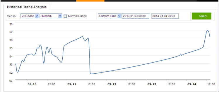
Pic.8 Historical Trend Analysis
4.2 Data Query
You can also query the historical data by lists. Go to Data reports ->Data Query. You can select the device and other conditions. The data can be exported in Excel.
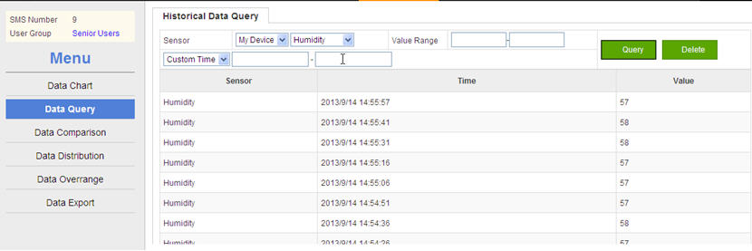
Pic.9 Data Query
4.3 Data Comparison
You can do comparative analysis between different sensors. Go to Data Report ->Data Comparison. For example, selectHumidity and Temperature, and the time period; then, right click on Query button. The comparative analysis will be shown below:
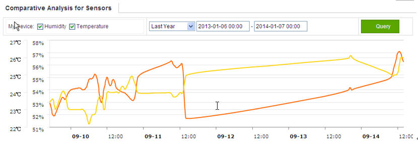
Pic.10 Comparative Curve
4.4 Data Distribution
You can check the data distribution. Go to Data reports ->Data Distribution. You can set the query conditions and the histogram will display.
.jpg)
Pic.11 Data Distribution
4.5 Data Overrange
You can set the normal range for your devices’ measurement. Go to Data reports ->Data Overrange to query the alarm statistics. Set the query conditions and the result will be displayed by pie chart.
.jpg)
Pic.12 Data Overrange
4.6 Data Export
Go to Data Report ->Data Export, click on Export to export the measurement list of specified device to local disk.
.jpg)
Pic.13 Data Export
5. SMS Alert
DeviceBit platform provides SMS alert service.To set SMS alert, the steps are as follows:
Step 1 Login to DeviceBit platform. Go to SMS Alert ->Contact List to check and add your contact list. You can appoint some contacts as your devices’ monitor so that they will receive SMS when your devices go into an alert state.
.jpg)
Pic.14 Add A Contact
Click on Add button to add the name and the telephone number of the person whom the SMS will be sent to. Then, click on Save.
.jpg)
Pic.15 Add A New Contact
Step 2 Go to My Devices ->Sensors&Controllers-
.jpg)
Pic.16 Sensor Edit
Click on Edit, fill in the Normal Value Range, tick On to enable SMS service and tick the person the SMS will be sent to, for example Alice and so on, and at last click on Save.
.jpg)
Pic.17 Enable SMS Alert
Since the settings are all set, you will receive SMS alert when the value exceeds the normal range.
6. Account Settings
6.1 Personal settings
Go to My Account ->Account Settings ->Personal Settings. You can modify your personal information here, such as your name, company Logo and so on.

Pic.18 Personal Settings Configuration
The user key is very important and unique for each account. The DeviceBit system distinguishes your gateways, devices and applications with others by different user keys.
6.2 TOP UP
Go to My Account ->TOP UP to top up your account as follows. Fill in the Card No., password and validate code if you have a top-up card. If you don’t have a top-up card please click on the link to buy one.
.jpg)
Pic.19 TOP-UP
6.3 Twitter
Go to My Account ->Twitter to bind your Twitter account.

Pic.20 Bind Twitter
Click on the button Bind, and your Twitter account is bound. Then, set the Twitter sending interval and at last click on Save.
6.4 Sub-account Settings
Once you have registered your account on DeviceBit platform, you can define several sub-accounts under your main account, giving the sub-accounts different authorizations. For example, one of your sub-account has the right to query without the right to add a sensor or a controller and modify personal information. Thus, your account is operated as an administrator, and could assign a number of sub-accounts. You can let somebody else maintain your equipment without having to worry that he accidentally delete or misuse your equipment.
Go to My Account ->Sub-account ->Add A Sub-user

Pic.21 Add A Sub-user
Click on Add A Sub-user to fill in the information, including the username, password, name and description, and then tick the items of operation rights for the sub-user. Thus, the sub-user could login to the system with the format Main-account: Sub-accountand change the password.
6.5 System Notice
DeviceBit system will send the users system notice if needed. Go to My account ->System Notice to check the system notice.

Pic.22 System Notice
You can acknowledge all the messages as already read or delete all the messages.
6.6 Change password
Go to My account ->Change password to change your password. Remember to change your password sometime for account safety.

Pic.23 Change Your Password
7. IOT Applications
7.1 Introduction
For senior users and enthusiasts, DeviceBit platform provides IOT applications. However, the ordinary users can not use these applications. Users who are interested in IOT can apply for these by sending an email to service@lewei50.com or by QQ technical support group (QQ group: 59162154).
7.2 Sending Twitter, Email or SMS
DeviceBit platform also provides functions of binding Twitter, email and SMS. The real-time measuring information of your sensor can be automatically sent to Twitter, emailed to the specified email address, or sent to a designated mobile phone number by SMS. Twitter content can also be customized according to different measured values. An example of Twitter auto-sending will be illustrated below. The sending mode of email or SMS is basically the same. You can select Twitter, email or SMS in the final auto-sending settings. So far, only Twitter is supported.
Cases
This case is to broadcast the humidity of the office by Twitter at different times(8:00am, 14:00 pm, 20:00 pm ). The microblogging content will be different according to different measured values. See the following example:
【DeviceBit NOTICE】:Good Morning! It is 2014-01-22 today, 11 o'clock. The current office humidity is 57%. It is comfortable!
Setting steps:
Step 1 Bind Twitter account. First, login to DeviceBit platform, go to My Account ->Twitter

Pic.24 Bind Twitter
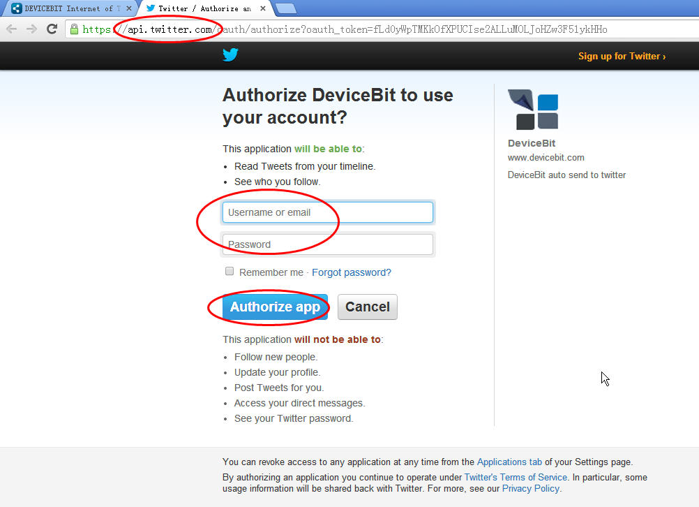
Click on Bind, a page will appear as follows:
Pic.25 Twitter
Enter your username and password, click on Authorize App and your Twitter account will be successfully bind. Note: If you have already login to Twitter, the system will automatically bind your account, and the login page will not appear. If you want to bind another account, you need to logout your Twitter first and restart IE browser before binding.
Note: For account security, the website to bind Twitter is api.twitter.com URL address.
Step 2 Set up variables. Click on IOT applications on the top, go to the menu on the left, and click on Variables Settings. Different Twitter sending content is defined according to different system variables or the measured value range of the sensor.
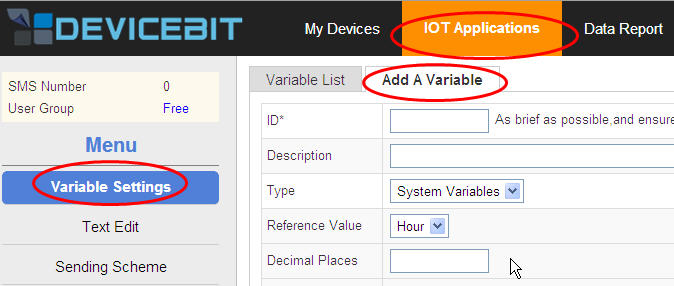
Pic.26 Variable Settings
First, set different Twitter content, Good morning, Good afternoon or Good evening according to the system variable Hour. Click on Add Expressions, and fill in the information as follows:
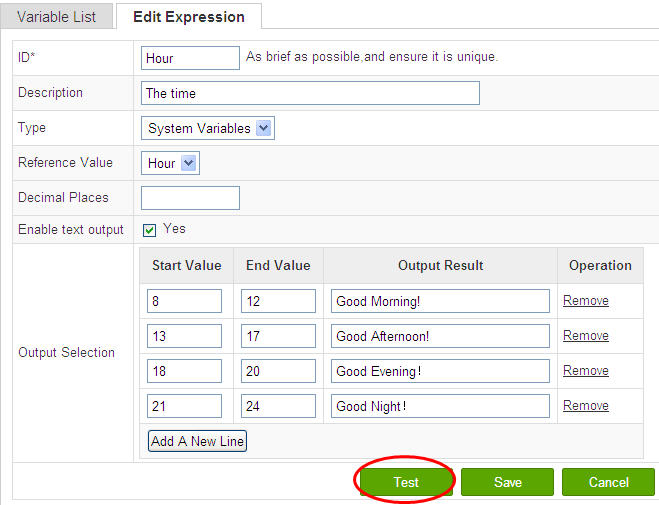
Pic.27 Hour Settings
Note the Type select System Variables . The system variables including the hour , date , and time. Select Hour here.Decimal Places leave blank, for decimal is not involved here. Tick Yes at Whether to output text? Then, click on Test, we can see that the current time is 11 o’clock, and the text is Good Morning! (For the time is at the range 8-12)
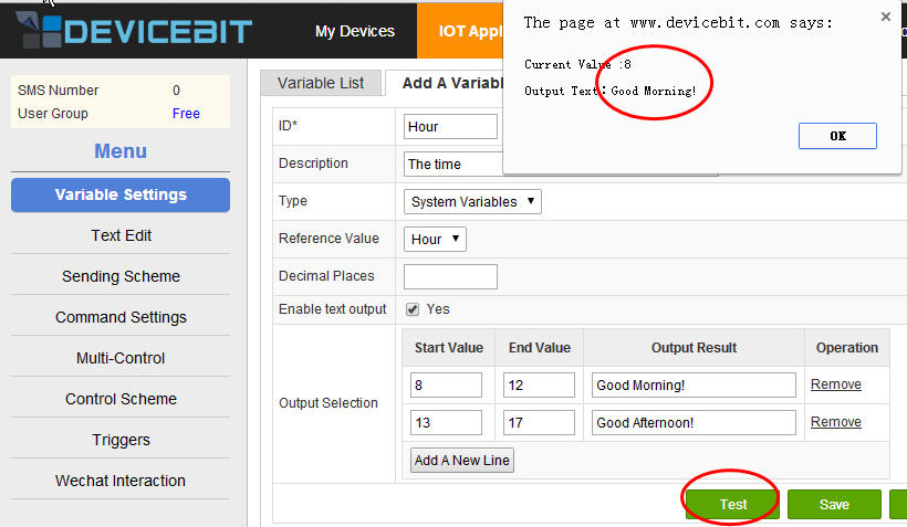
Pic.28 Test For Hour
Next, set up Date in the same way. Settings for date are very simple. Ignore Enable text output for there is no need to set it. The settings and test results are as follows:
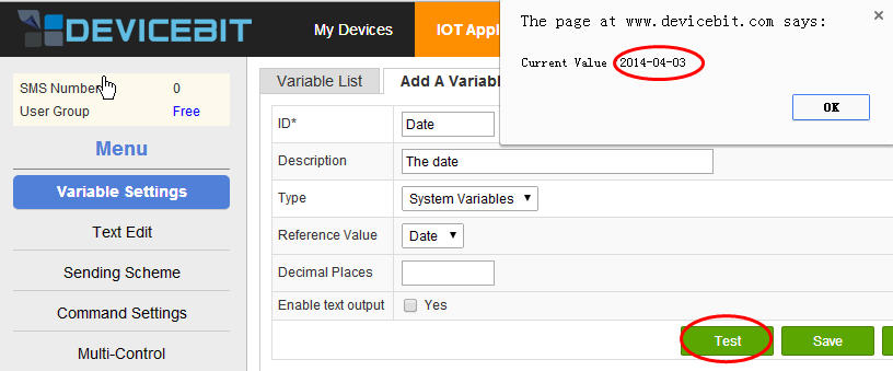
Pic.29 Settings &Test For Date
Finally, set the Twitter text according to different measured humidity values. Here, select Sigle Sensor for Type, select My Device and Humidity for Reference Value. Since all the values are integers, the decimal places do not need to be set. If the measured values are decimals, you can set the decimal places here. The format is .0, .00 and so on. The logical relationship between the output text and the value range is as follows, and you can define it by yourself. Then, click on Test to check the result.
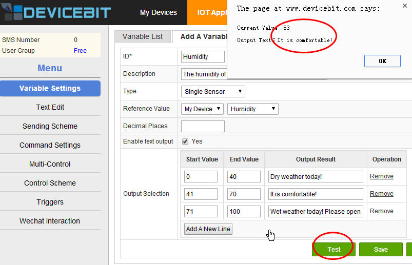
Pic.30 Settings & Test For Humidity
The above settings for variables are complete. Of course, there are more settings for more complex logical relationships. You can select Sensor Group for Type, and Average or Sum and so on for Synthetic Pattern. You can select multiple sensors and do more researches by yourself.

Pic.31 More Complex Settings
Step 3 Edit text: Click on Text Edit ->Add Sending Content
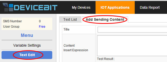
Pic.32 Text Edit
The settings and test result are as follows.
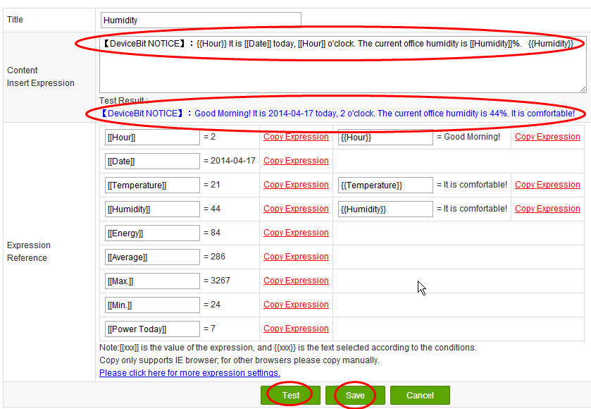
Pic.33 Settings & Test For Text
The returned content for [[ ]] is the returned value of the system variable in [[ ]], the measured value of the sensor in [[ ]], or the more complex logic operation result of the measured values of the sensor in [[ ]]. For example, the returned content for [[date]] is the current date. While, the content for the two braces {{}} is the Twitter Text corresponding with the value range of the variable in {{}}. For example, in the following picture, the current humidity is 57%. According to the previous logic relationship set for the value range from 41 to 70, the returned text content for {{Humidity}} is It is comfortable! After setting, you can click on Test to see whether the settings are correct.
Step 4 Set up auto-sending settings. This step is very simple. Click on Sending Scheme ->Add Auto-sending Settings. SelectTwitter for the Sending Type. Select Every Day for the Repeat Type. Tick the time, for example 8:00, 14:00, and 20:00. Then the text content will be sent to Twitter automatically at 8:00am, 14:00pm, and 20:00pm everyday!
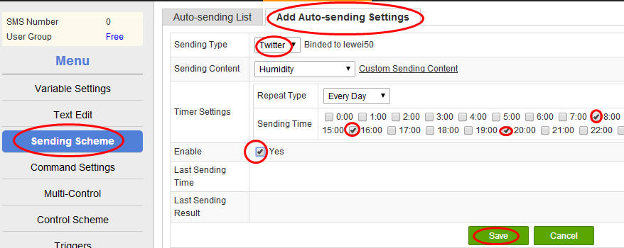
Pic.34 Auto-sending Settings For Twitter
The above settings are all completed. Thus, you can see different Twitter sent automatically at the defined time according to different measured values by your Twitter account bound.
The sending mode for E-mail and SMS is the same with Twitter. Just select E-mail or SMS at Add Auto-sending Settings. After selecting, there will be a blank column for you to fill in the E-mail address or mobile phone number.
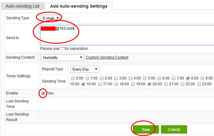
Pic.35 Auto-sending Settings For E-mail
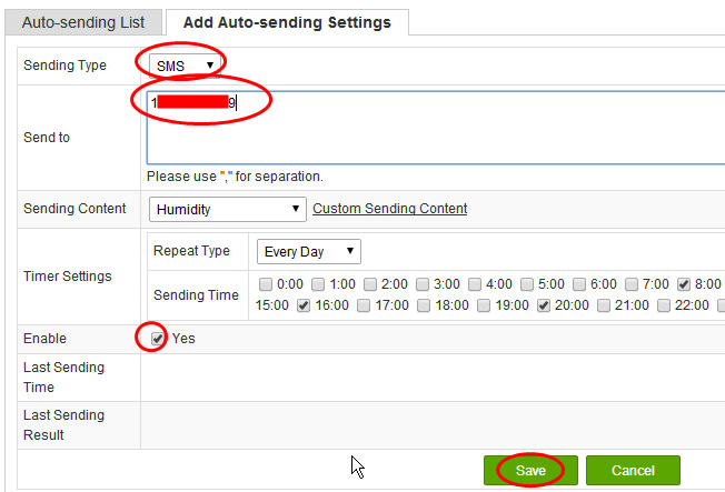
Pic.36 Auto-sending Settings For SMS
7.4 Control Scheme
The Devicebit platform also provides settings for custom commands and timed control scheme to realize various timed custom control. The following part mainly introduces this function.
Step 1 Command Settings. Go to IOT Applications -> Command Settings, and right click on Add A Command.

Pic.37 Add A Command
Title: The name of this command;
Device: select the controllable device;
Method Name: select Updatesensor, or customize the method by yourself;
Parameter: When this command is called, the transfer functions of this device's API address is called. Please note the format is “f=method name, p1=parameter1,p2=parameter2…”
The method names and parameters are related to the program. Please refer to this document http://www.lewei50.com/home/news/92 for detail.
Add other control commands in the same way, such as Open LED and Close LED. Click on Test, and if the hardware and program are ready, you will see a corresponding change in the controller. You will receive the successful message and the information returned by the controller.
Step 2 Control Unit Settings. IOT Applications -> Multi-control. The control unit means a set of timed control command, e.g. a combination of control commands.

Pic.38 Add A Control Unit
Name: the name of this control unit;
Command: select one or a set of several commands customized in step1;
Description: the description of the control unit.
After setting up, click on Multi-Control – Test for testing.
Step 3, Control Scheme. Click on IOT Applications -> Control Scheme -> Add A Execution Plan to set up the control scheme.

Pic.39 Add A Execution Plan
Control Unit: select the control unit customized in step2;
Name: the name of the control scheme;
Timer Settings: the time to execute the control unit; just tick the time you need;
Enable: tick means On; untick means Off.
After setting up, click on Execute Immediately for testing.
The above are settings for timed custom control plan. You can realize various interesting timed control with different hardware and ideas, for example Auto-open your curtains at 7:00 am before you get up.
Tip
For any questions, please contact DeviceBit Customer Service
xujing@devicebit.com, support@devicebit.com
Tel: 0086-10-52981332
Mobile: 0086-13911890238
